Step 3: Connecting the Wall Boxes to the In-Store Wiring
| 1. | Decide where to mount the Wall Box: |
| • | Provide at least 10 cm (4 in.) of clearance around the mounted wall box for cable connections. |
| • | Plan to mount the wall box within 3 m (10 ft) of the workstation. |
| • | The location must be physically protected but still accessible for maintenance. |
| • | Plan to mount the wall box with the connector opening downward or horizontal so that liquids or other debris cannot enter the box. |
| 2. | Assemble the following tools: |
| • | Insertion tool (NCR P/N 603-9009892 or AMP P/N 552714-3) |
| • | Cable stripping tool |
| • | A drill with a 6.35 mm (0.25 in.) to 4.76 mm (0.1875 in.) bit (for screw mounting) |
| • | A screw driver (for screw mounting) |
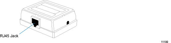
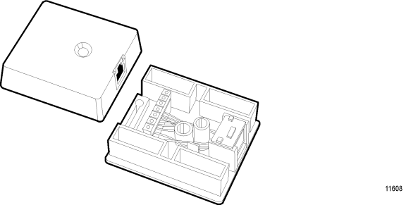
| 3. | Remove the cover of the wall box by pressing the retaining clips located along the front edge of the wall box cover. |
| 4. | Mount the wall box base assembly to the wall, with the connector pointing down or sideways, using the adhesive tape or the mounting screws provided. |
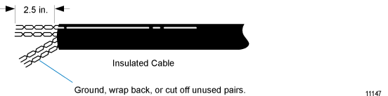
| 5. | Prepare the twisted pair wire by stripping the jacket 6.35 cm (2.5 in.). |
| 6. | Locate the insulation displacement terminals on the PC board of the wall box. |
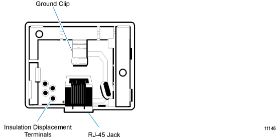
The following procedure details the connection of twisted pair wire to the Wall Box.
Caution: All twisted pair wire has a twisted pair dedicated to transmission, and another pair to reception. DO NOT BREAK THESE PAIRS. Your system will be wired incorrectly if you do.
Note: Some non-NCR wall boxes may use screw terminals instead of insulation displacement terminals. In this case, use the following pin connections in order to interface to an RJ-45 modular plug.
NCR Wall Box and Cable
|
Signal |
Color |
Terminal |
RJ-45 Connector Pin |
|---|---|---|---|
|
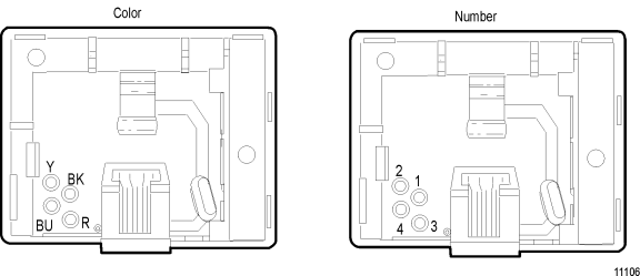
Transmit (+) |
Black |
1 |
1 |
|
Transmit (-) |
Yellow |
2 |
2 |
|
Receive (+) |
Red |
3 |
3 |
|
Receive (-) |
Blue |
4 |
6 |
AT&T WE 103A Wall Box
NCR Wall Box and Cable
|
Signal |
Terminal/Color |
RJ-45 Pin/Color |
|---|---|---|
|
|
1 White/Blue |
5 White/Blue |
|
|
2 Blue |
4 Blue/White |
|
Transmit (+) |
3 White |
1 White/Orange |
|
Transmit (-) |
4 Yellow |
2 Orange/White |
|
Receive (+) |
5 Red |
3 White/Green |
|
Receive (-) |
6 Black |
6 Green/White |
|
|
7 White/Brown |
7 White/Brown |
|
|
8 Brown |
8 Brown/White |
| 7. | Insert wires into the insulation displacement terminals: |
| a. | Place the wire over the terminal slot with the end of the wire touching the back inside wall of the terminal. |
| b. | Position the tool on the terminal so that the wire enters the slot in the tool shank. |
| c. | Press straight down on the tool handle until the tool stop bottoms on the terminal. Remove the tool from the terminal. DO NOT tilt or twist the tool as this may break off the insulation displacement terminal. |
Note: If you are using shielded cable, the cable shield must not be exposed to the outside of the wall box.
| 8. | Position the cable carefully inside the base and snap the plastic cover in place. The cover provides both strain relief for the cable and protection for the PC board. |
